Rockwell Hardness Test
The Rockwell hardness test is a non-destructive testing method performed by comparing depth of indentations. The test is defined in ASTM E-18 and ISO 6508-1. The hardness test is named after the inventor of the Rockwell hardness tester machine invented by Hugh Rockwell and Sanley Rockwell, although the differential depth hardness measurement was developed by Paul Ludwik in the book Die Kegelprobe in the early 1900s.
The Test Method
The test is performed using a steel ball indenter or spheroconical diamond indenter with different physical dimensions depending on the Rockwell hardness scale the material is being tested against. A minor load is applied to the surface of the material to establish a zero position (held for a predetermined length of time). A major load is applied with a force depending on the Rockwell Hardness scale the material is being tested against (held for a predetermined length of time). The difference in depth between the zero position and the permanent depth after the major load is released is used to determine the hardness number.
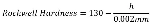
The Rockwell hardness equation is:

Where:
‘N’ is a factor specific to the Rockwell hardness scale the material is being tested against.
‘h’ is the measured difference in indentation measured in mm.
‘s’ is a scaling unit based on the Rockwell hardness scale measured in mm.
According to the ASTM E-18 documentation, the Rockwell hardness is determined as follows:
Using a diamond spheroconical indenter:


Using a ball indenter:

The Rockwell hardness test is recommended to be used on material at least 10x thicker than the indentation depth. The superficial scale uses a lighter load and can be used for thinner material.
The hardness numbers are linearly proportional to tensile strength numbers and can be compared using reference charts that have been developed by performing non-destructive hardness tests and destructive tensile tests on the same material samples.
Design Considerations
Design engineering requirements for material meeting specific minimum hardness numbers must be followed strictly by manufacturing engineering processes to produce a part that works as intended. Incorporating machining, welding, and other manufacturing processes will change the molecular structure of the materials. Therefore, critical features should incorporate changes to local material hardness throughout the manufacturing process.
A common example is determining the heat affected zone of a welded joint. Is it near any critical part or assembly features? What is the designed minimum hardness requirement for the feature to work as intended? At what distance away from the welded joint does the material meet the requirement? How will a larger weld, smaller weld, different weld wire, weld type, etc. affect the heat affected zone? The heat affected zone of 6061 aluminum can cause the material to completely anneal at the closest point to the welded joint.
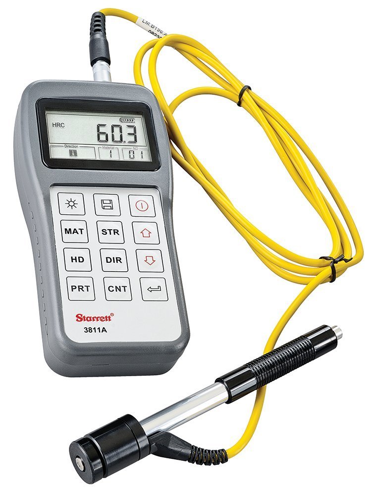
Portable Rockwell Hardness Testers
Starrett 3811A Compact Portable Hardness Tester -- Amazon
Jarrett Linowes
Mechanical Engineer
omniamfg@gmail.com
Did I miss anything you are interested in? Send me an email or comment below!