Omnia MFG is focused on closing the information gap between Mechanical Design Engineers and Manufacturers.

WELDING
Welding Standards - Engineering Drawings - Elements of the Weld Callout
It is easy to fall into a designer’s bubble and not take the time to fully understand the industry that will be building your designed part. In engineering, and arguably in every industry, words are very loaded, and people do not take the time to fully understand their impact on outcomes. Designing a welded joint is not a simple matter, and in many cases an over-engineered joint can result in a poorly built product.
The term weld brings with it weld process, type of weld joint, filler metal, heat affected zone and material temper, porosity, distortion, material shrinkage, structural integrity, etc. Most of these terms and potential issues will be taken care of by the manufacturing factory involved in the project, but it is important for a design engineer to understand the process.
In the design engineer’s mind, they should be also focused on the next higher assembly, interface/interference analysis, type of weld joint that will comply with requirements while reducing preparation time and potential fixture development, machinability, environmental effects on the part, etc.
Designing a welded assembly or part to be used by the public must follow stringent standards developed for safety by organizations and governments worldwide. These standards offer peace of mind by manufacturers and to designers by providing easy-to-follow welding guidelines that will result in properly engineered joint construction. Although designers must choose the proper materials for the application and perform a subsequent structural analysis of the product, the standards make it possible to design welded joints with the understanding that the theoretical engineering will not be lost between groups involved.
Welding Standards
Welding specifications and standards, like many other standards reports, should not be taken as absolute best practices, but instead, popular science and engineering practice with experience and results to backup the claims.
Standards are phenomenal resources to use and learn from because they allow you to see the perspective of each person in the design and manufacturing lines. By understanding the standards, you will be able to make more informed decisions on welded joint design rather than simply stating “weld per AWS d17.1” and unintentionally causing a part to become more expensive or be built poorly by a manufacturing factory.
Below are standards commonly used in the United States of America, but there are hundreds of others available, and generally local to a country or a company.
ASME Codes -- American Society of Mechanical Engineers -- Include welding specifications integrated into the design and manufacturing standards.
AWS Standards -- American Welding Society -- Code standards written as guidelines for welding in generalized and niche topics ranging from AWS D1.2 (Structural aluminum welding) to AWS D18.3 (Hygienic equipment welding).
ISO Standards -- International Organization for Standardization -- Thousands of inclusive guidelines and standards covering weld process specifications and classifications for the majority of modern techniques.
Other weld standards available are localized to countries or regions such as the Australian standards (AS/NZS), Canadian Standards Association (CSA), European Union (CEN), British Standards (BS), and others. Choosing a standard to design with will be influenced by the end customer and preference for depth of standardization. All of these organizations overlap in information and standardization, and in some cases, are written based on each other. For the purpose of keeping everything consistent, this page will focus on the AWS standardization documents.
Engineering Drawings
The purpose of engineering drawing weld symbols is to create a channel of communication between designers, engineers, and manufacturers. Weld symbols on drawings should be understood through the design and manufacturing pipeline, including shop floor personnel.
With a single leader-line arrow symbol, a design engineer can communicate the type of weld, joint preparation, length or depth of weld, location of weld, quantity of welds and spacing, and can refer the interpreter to relevant notes or other locations with identical joints.
How to read a weld symbol
A weld callout (a grouping of weld symbols informing the interpreter of the entire joint welding process) includes weld symbols and any other relevant information all standardized on a leader arrow.
The arrow connects the weld callout to one side of the joint to be welded.
The longer line includes all elements defining the joint preparation and the weld size, location, etc. requirements.
The split lines on the end are optional, called the tail, and include any other specification or reference information.
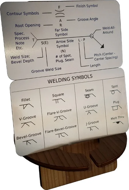
Below is a detailed representation of a weld symbol callout using the AWS standards for location of information. The information is generally the same between the AWS standards and ISO standards, but the numbers may appear in different areas of the leader arrow.
Below are example weld callouts that use the above weld symbol diagram as a reference. Some not very obvious differences are the location of the contour and finish symbols and the field flag symbol.
- The finish symbol is almost always located along with the contour symbol directly under or next to the weld symbol.
- The groove angle and root opening is located on the side of the weld symbol it is pertaining to.
- The field flag indicates that this weld will be completed on the part during or after installation (in the field or on the next higher assembly).
Example 1:

Example 1 shows a .25” fillet weld located on the nearside (or arrow-side) of the welded joint. The weld is designated “all-around,” indicating that the weld on the joint is continuous until it connects with itself. The weld is then contoured using a grinding pad.
Example 2:

Example 2 shows a .12” V-groove weld with a .19” effective size (or penetration) located on the nearside of the welded joint. The weld is intermittent along the entire joint with a length of 1.25” and a pitch (center to center spacing) of 4.00”. The weld is then machined flat to the member surface. The weld has a “2X” indicator in the tail of the callout, indicating that the entire weld callout is used in 2 places that have typical joints.
Example 3:

Example 3 shows a .25” plug weld with a countersink angle of 45 degrees located on the nearside of the member face. The quantity of welds is 4 with a center to center spacing of 2.25”. The weld is also indicated to be performed in the field on the upper level assembly rather than as an isolated part. The tail of the callout references a note 4 that pertains specifically to this weld.
Designing with Weld Symbols
Designing the weld requirements on a part can be based on strength, corrosion, EMI shielding requirements, environmental requirements, anticipation for material movement, and others.
Fixturing
Precision parts will likely involve tight GD&T boundaries that will ultimately lead to custom fixtures developed for the welding process. Limiting the tight requirements to anticipate material movement during weld will greatly reduce the manufacturing costs.
Weld sizes
Minimum weld sizes differ between types of welds and standards. AWS structural welding codes should be consulted as well as customer proprietary codes if necessary while designing a weld joint. In all cases, a parallel structural analysis and other tests should be conducted to verify the information available in the standards apply to your project. For example, the minimum fillet weld size for a welded steel joint, where the thicker material is less than .25”, is .125” (AWS D1.1: Structural Welding Code – Steel, Table 5.8).
Corrosion
Corrosion largely affects the lifespan of a product and repair cycles. In many cases, even with a matched filler metal, the weld joint heat affected zone will likely corrode at a different pace from the base material due to the difference in chemical composition.
A short article by Lyndsey Deckard shows the possible effects and how to evaluate corrosion resistance: https://app.aws.org/itrends/2007/07/it200707/it0707-32.pdf.
Strength and Quality of Welds
Structural analysis should be performed for welded parts. Depending on the factor of safety accounted for, nondestructive tests (NDT) may be required to guarantee the weld was performed correctly. NDT include dye penetrant inspection, ultrasonic testing, magnetic particle inspection, etc.
Elements of the Weld Callout
The weld callout is the portal from the designer’s mind to the manufacturing personnel handling the project. In many cases, missing information or misinterpretation of a weld callout can cause major project delays and incur unexpected costs while working with the manufacturing partner.
Included on the leader line is a weld symbol type and an indication of near-side or far-side, a length, pitch, weld size, contour symbol, finish symbol, and other reference information. The below two tables explain the various elements.
| Weld Callout Symbols | |||
|---|---|---|---|
| Finish Symbols C, G, H, M, P, R, U Post processing of a welded joint: Chip, Grind, Hammer, Machine, Planish, Roll, Unspecified. |
Contour Symbols ) ( | Post processing to form a concave, convex, or a flat contour. |
Groove Angle A Total angle formed between the groove faces on the weld joint. |
Root Opening R Groove welds - Open space between welded members to help with weld penetration. Plug/Slot welds - Depth of filling. |
| Far Side/Arrow Side Far side - Joint opening on opposite side of feature or plane with respect to leader line. Arrow side - Joint opening leader line is pointing to. Both side weld callouts can be mirrored or staggered in intermittent. |
Weld Size and Bevel Depth S Fillet weld size and bevel/v-groove preparation depth. |
Groove Weld Size (E) Actual depth of penetration of groove weld. |
|
| Number of Spot, Plug, and Seam Welds (N) |
Length L Length of welds if the weld does not span the entire joint or if the welds are intermittent. |
Pitch P Center to center spacing of intermittent or staggered welds. |
Weld-All-Around O Weld or intermittent weld is continuous around a single joint/feature and meets back to the start point. |
| Specifications, Process, Notes, Etc. T Additional information regarding the weld specification, weld wire, changes to the preparation, and other notes. |
|||
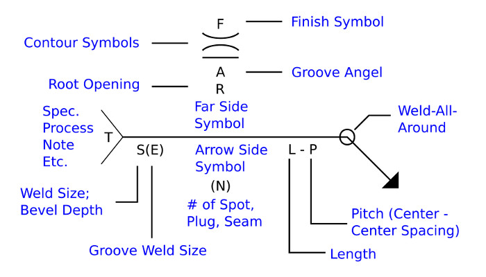
Weld Symbols

Fillet Weld

Square Weld

Seam Weld

Spot Weld

V-Groove Wled

Flare-V-Groove Weld

U-Groove Weld

Plug Weld

Bevel-Groove Weld

Flare-Bevel-Groove Weld

J-Groove Weld

Weld Melt Through
Jarrett Linowes
Mechanical Engineer
omniamfg@gmail.com
Did I miss anything you are interested in? Send me an email